
From the CAD model to a robot that is actually cutting
None of this is a roadmap. It is the pipeline that produced parts on a real cell: two ABB IRB 6650S on 20-metre tracks, fifteen-metre mould plugs, 118,417 points solved in a browser tab. Every link below is listed together with the thing that usually goes wrong there, and with the place where we catch it.
- 13,081,290points solved on the platform so far — and counting
- 381writes to live controllers, each in an audit chain
- 10Hzlive telemetry from the controller
- 15mmould plugs on the reference job
- 2× 20 mrobots on tracks, working at the same time
Seven links
Each link does one job and fails in one characteristic way. The point of building it as a chain is that the failure surfaces during conversion, at a desk, and not at the robot with a spindle already in the part.
CAD and CAM
The part and the machining strategy stay in the CAM system your people already use — today that is Fusion 360, through an add-in that exports the cell scene and the toolpath.
Caught hereUnits and axis conventions drift apart: Fusion works in centimetres, the logic in millimetres, the 3D view in metres, and design and the controller program are Z-up while the viewer is Y-up. Conversion happens only at layer boundaries, through a single function, covered by tests.
Toolpath import
APT and G-code are parsed into an ordered set of positions and tool orientations expressed in the frame of the cell.
Caught hereA file that parses cleanly but means something else. Unsupported constructs — drilling cycles, subprograms, non-identity coordinate systems — are reported with a severity and a line number, so you see what the import did not take before you cut anything.
Inverse kinematics with joint limits
Every point becomes six joint angles plus a position on the track, with the tool orientation the process requires held throughout.
Caught hereA pose the arm cannot reach, or an axis that runs past its limit halfway down a fifteen-metre part. Soft joint limits turn what would be a controller error at run time into a FAIL during conversion, reported at the point that caused it.
Collision checking
Robot against robot and robot against part, on the real meshes, with the neighbouring robot present in the scene as a translucent ghost.
Caught hereBatch checking walks the path with a stride, so a very brief collision between two samples can pass unseen. Where a hit is found, the bounds of the colliding region are refined point by point around it; a stride of one checks every point. The simulator never replaces the cell’s own safety systems.
Cycle time
The estimate accounts for acceleration and deceleration, not just path length divided by feed rate.
Caught hereA quotation built on a feed rate the machine never actually reaches, which is how a job becomes unprofitable before anyone switches it on.
Post-processor
The controller program comes out the other end: feed ramp-up, deceleration into corners, zone data, and the program split into modules the controller can load.
Caught hereA program that is correct but too large for the controller to load. Splitting is part of the export rather than a manual rescue. On the reference job, 299 .mod files came out byte-identical between the local and the server pipeline.
Into the controller
The program is uploaded to the controller over the local bridge. From then on the window shows live telemetry at roughly 10 Hz and the program line the robot is executing right now.
Caught hereThe right program in the wrong controller — on IRC5 every service port carries the same address. The window reads the identity out of the controller and compares it with the one the cell document expects.
The cell is a document, not a fact baked into the code
Robot, mounting, track, tool, work object frames and the roster of robots live in one document that describes your cell. The kinematic core receives it as a parameter: the same code runs in the browser tab and on the server, and moving to a different cell is a different document rather than a different build.
- Robot and geometry
- Link lengths and joint limits come from the document, so the tab computes with the same arm the server does.
- Mounting
- Floor, track or pedestal.
- Tool and work objects
- Tool mount, TCP, and the work object frames the program is written against.
- Roster
- Which robots are in the cell. A command can only be addressed to a robot on that list, and the address of the operator window names both the cell and the robot.
Everything above the controller is vendor-neutral by construction: the kinematic core is a pure function, the cell is a document and the robot arrives as a parameter. Two things are written per controller — the post-processor that emits the program and the driver that talks to the machine while it runs. The current production adapter writes RAPID and speaks to ABB IRC5; for another controller both are engineered and verified on your cell, as a scoped line in the delivery, not a promise that it already exists. Two robots working at the same time are proven in production; the neighbour ghost and the proximity guard are pairwise today, so three robots or more need an all-pairs guard. That is project work, not a switch.
Calibration and measurement, or the part comes out wrong
A simulation is a drawing until the numbers inside it match the steel on the floor. Two of them do most of the damage when they are off: where the tool tip actually is, and where the part actually sits.
- TCP from four points
- The tool tip is found by touching one point from four orientations. The result goes into the cell document, not onto a sticky note.
- Part position from sketches
- Probe points defined as sketches in Fusion are measured on the cell, and the work object frame is corrected against what was measured.
- Work objects read and written
- The window reads the frames out of the controller and writes them back, so the drawing and the controller do not each hold their own truth.
- Corrections
- Small offsets can be applied without regenerating the whole program.
The operator window is a browser tab
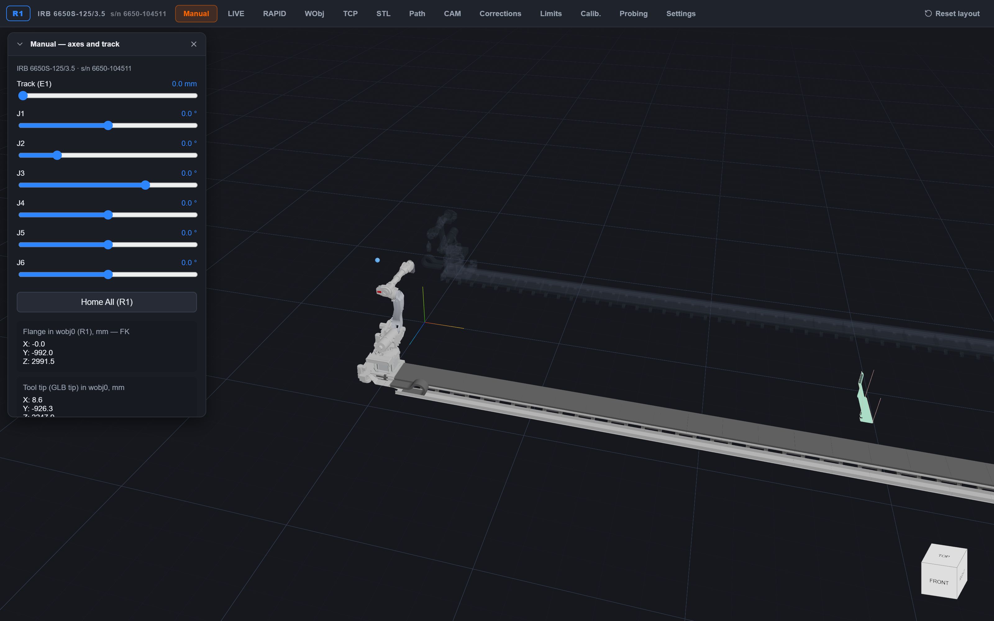
Nothing is installed on the shop-floor PC. The window is addressed per robot: one window is one robot, two robots means two windows on two screens, and that is also how a licence is counted.
- Live telemetry
- Joint values and tool position at roughly 10 Hz, with the neighbouring robot drawn as a translucent ghost.
- Current line
- The program line the controller is executing, next to the path segment it belongs to.
- Manual jog
- Axes and track, from the same window.
- Timeline
- The solved program plays back and scrubs before anything is sent to the controller.
The application also runs completely on its own — no back end, no bridge — which is what makes it usable for reviewing a job away from the cell.
Who may do what, and what is left behind
A window that can overwrite a program and start a robot needs an answer to “who did this” that holds up when someone would prefer a different answer.
- Three roles
- Viewer, operator, technologist. A token is issued for one specific robot, so access to one cell is not access to the next one.
- Verification without the internet
- Tokens are short-lived and signed with Ed25519; the bridge checks the signature offline, with a public key it already holds.
- Append-only audit trail
- Every write to the controller is a record carrying the hash of the previous one. The record is written before the controller is touched: who tried matters as much as who succeeded.
- External anchor
- The head of the chain is shipped out of the cell. A chain kept only on the box next to the controller catches a careless edit, but not someone who recomputes the whole file.
- Separated database roles
- The application role has no UPDATE or DELETE on the anchor table. An append-only rule that only the application obeys is not evidence.
Emergency stop is deliberately outside the token and outside the internet. Gating it would make stopping a robot depend on a correctly configured secret; the asymmetry is obvious — an unauthorised stop is downtime, a blocked stop is a collision. It is still not a safety function within the meaning of the Machinery Directive: that is the cell’s own two-channel chain on the pendant.
Where this physically sits
The bridge that talks to the controller runs next to it, on the shop network. In a cell with one robot that is often just the shop-floor PC. In a cell with two it is a small box per controller, because on IRC5 both service ports carry the same address, and no amount of routing gets around that.
Operator windows in the shop are served locally, so the guard that keeps two robots apart never waits on an internet connection. The cloud is for what happens away from the cell: reviewing paths, preparing programs, holding the audit anchor.
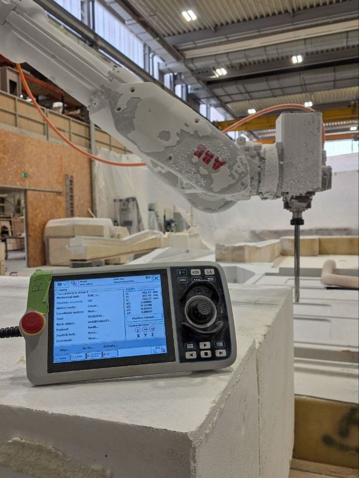
Потрібне фото
Коробка CM4 на дроті біля шафи IRC5, вертикаль: видно кабель, що йде в сервісний порт X2, і стяжки. Це апаратний ключ — маленька коробка поруч із промисловою шафою доводить тезу краще за будь-який опис.
Where the line is
- Milling is the proven process. Polishing, finishing, coating and large-format printing are the same class of continuous contact path and are scoped per project. Machine tending is a different class of motion — there is no trajectory, there are points, grippers and an I/O handshake with the machine tool — so the motion layer is written new.
- Robot geometry today is the IRB 6650S. A catalogue of models is planned work, and it carries a real risk of TCP shift, so it is done under contract rather than speculatively.
- The simulator is an auxiliary engineering tool. It is not a safety function within the meaning of the Machinery Directive and does not replace the robot cell’s own safety systems.
- There is no self-service sign-up. Every delivery starts with a look at the actual task.
Does this match your cell?
Tell us which robot it is, what it should be making, and what is already in place. If the honest answer is that this is not a fit, that is the answer you get.
Tell us about your robot